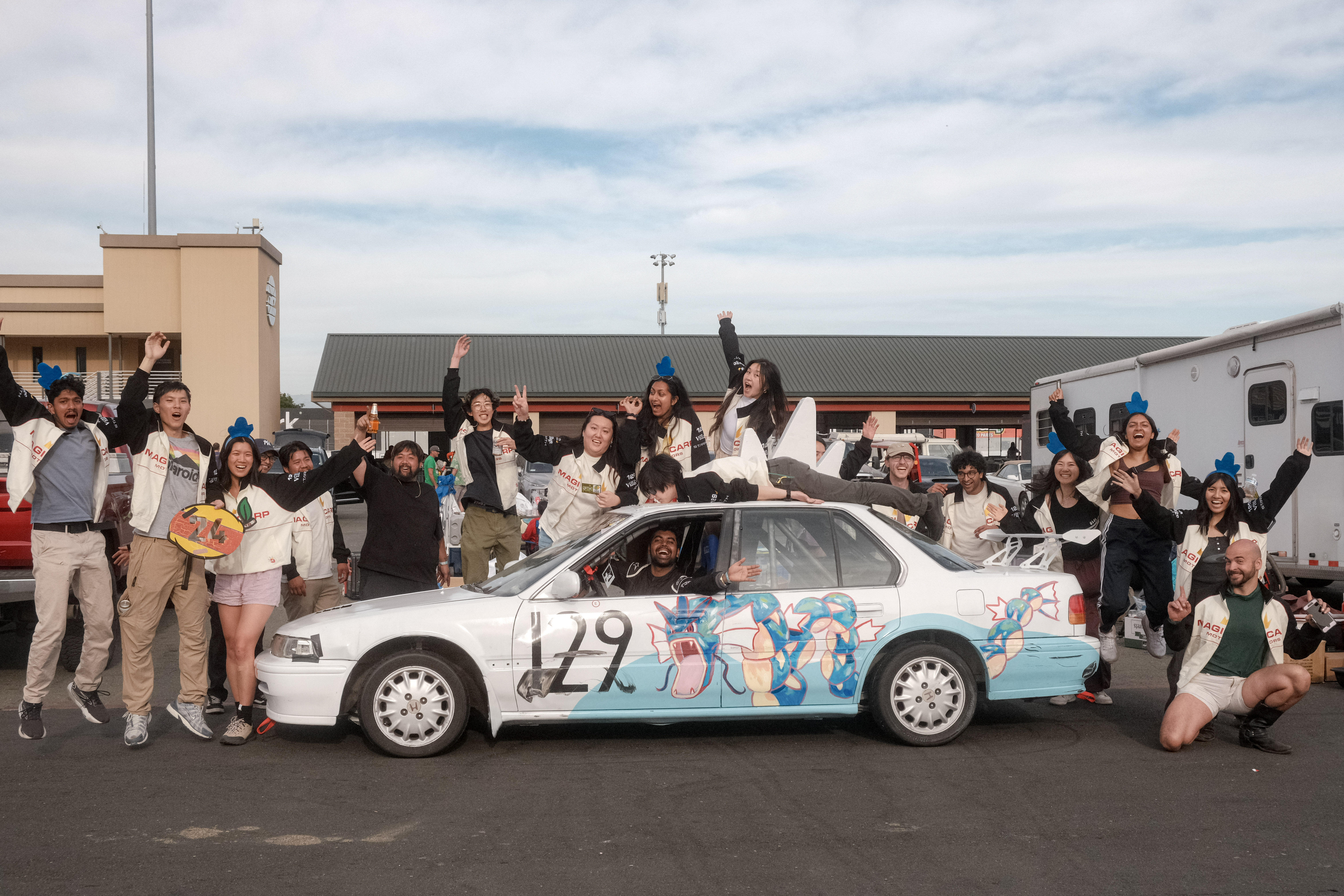
Outside of work, I lead a 24 hours of lemons endurance racing team. For our Spring 2026 Sonoma Race, we needed to build a custom telemetry system that could:
- Give a realtime camera feed of the driver POV
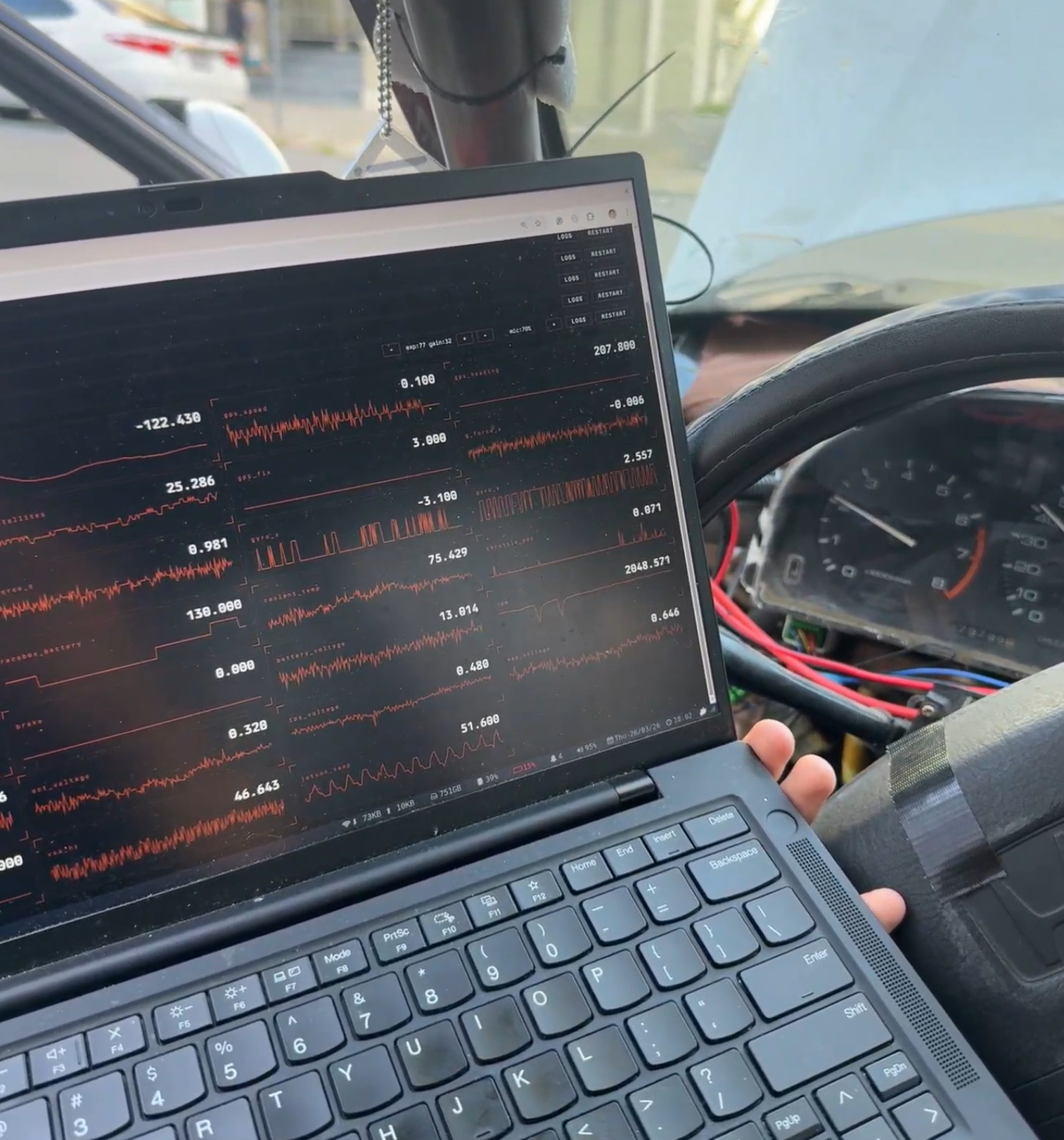
- See a realtime dashboard of critical engine/car/driver-input telemetry
- Stream all of this to a livestream for spectators and audience abroad
This was a ton of fun to get to apply all my skills from Orchard Robotics and SpaceX to an engineering project to directly make my friends happy.
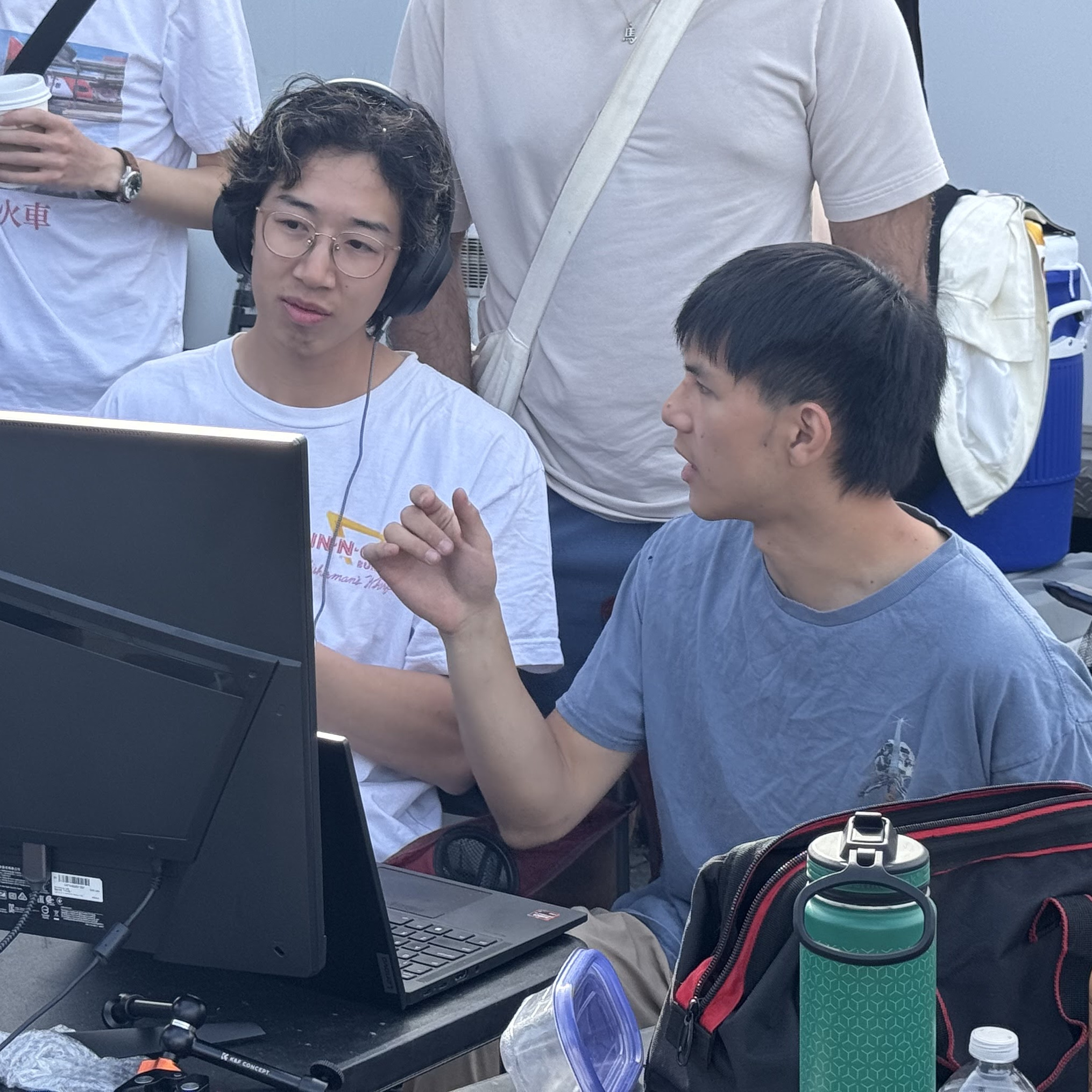
I designed the hardware architecture, wrote the embedded software, and built the physical system. Jacky built out the entire software stack and data-flows. And of course, the rest of the team built the race car.
- Check out our team’s GitHub: https://github.com/shihaocao/telem
- Check out our team’s IG here: https://www.instagram.com/magicarpmotors/
- And check out Jacky’s blog post here:
COMING SOON
In the rest of this blog, I’ll talk about the hardware design and build out.
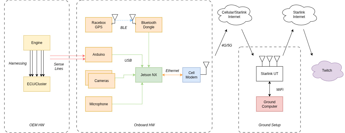
01 - HW Architecture
Design Considerations
We had considered a Starlink Mini as vehicle data offload but decided against this because I was unsure if we would be in a garage. Because Starlink does not work without line of sight, we went for cellular backhaul off of the vehicle.
The need for multiple camera POVs, as well as pulling in data from multiple diverse sources essentially forces a Jetson-like central OBC.
We had also considered running the stream on the vehicle, but this would have been very rough as the stream would have died if the telemetry computer restarted. So keeping that separate was a great choice.
Nailing down the HW architecture was the first step in the process. This was very similar to systems I had built in the past at Orchard Robotics, so it felt like home turf.
02 - Hardware BOM
| Component | Model | Specs | Power | Cost | Category | Notes |
|---|---|---|---|---|---|---|
| Forward Wide Camera | Logitech C920x | 1080p × 30fps | USB 2.5W | $70 | Video | Driver POV |
| Driver Camera | Logitech C920x | 1080p × 30fps | USB 2.5W | $70 | Video | Shifting and pedal movements |
| On Board Compute | Jetson Orin NX | 16GB RAM, NVENC accelerator | 12V/5A → 60W max | $1150 | Compute | Hardware encoding accelerator avoids video bottleneck |
| 5G Modem | GL-X3000 | 5G, physical SIM | 12V/2.5A → 30W max | $323 | Connectivity | |
| SIM Card + Plan | Visible+ Pro | Unlimited data | — | $45/mo | Connectivity | Verizon works well at Thunderhill and Sonoma |
| GPS/Accel | RaceBox Micro | 25Hz, <1m accuracy | 12V, 0.2W max | $125 | Telemetry | Also works as standalone product with phone |
| Bluetooth Dongle | UD100-G03 | BLE 4.0 | USB, 2.5W max | $39 | Telemetry | Jetson lacks built-in BT; needed for RaceBox BLE |
| Microcontroller | Arduino Mega 2560 | 54 digital I/O, 16 analog inputs | USB, 1W max | $49 | Telemetry | Overkill; smaller 5V Arduino would suffice |
| Microphone | LavMicro-U | USB lavalier | USB, 0.5W | $30 | Audio | In-car audio, Opus 64kbps |
One of the earliest things I derisked was whether or not the modem would even work with the Visible physical SIM card. I had to borrow a friend’s Android with a physical SIM card slot, activate it, then transfer the sim and hope everything would “just work”. Luckily, despite online sources reporting otherwise, it did.
03 - Telemetry Points
Tapping Strategy
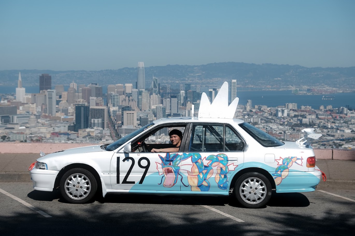
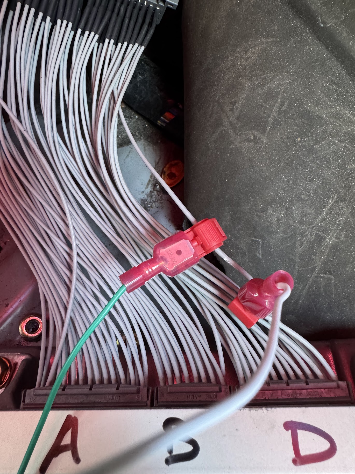
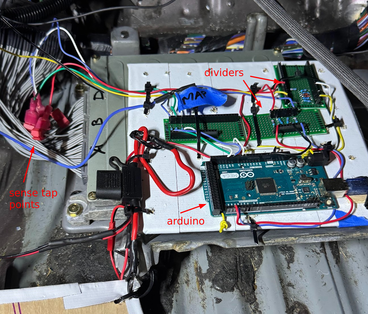
Since the 1992 Honda Accord is before the OBD2 era, we needed to grab most of our telemetry points via analog sense taps. For 12V signals, this would require a voltage divider circuit. For 5V signals, as long as we use a 5V microcontroller we can skip the voltage divider.
Finding what pins to tap where was a slow and tedious process.
- Figure out what line to tap via FSM + Haynes
- Tap the line via t-splice connectors
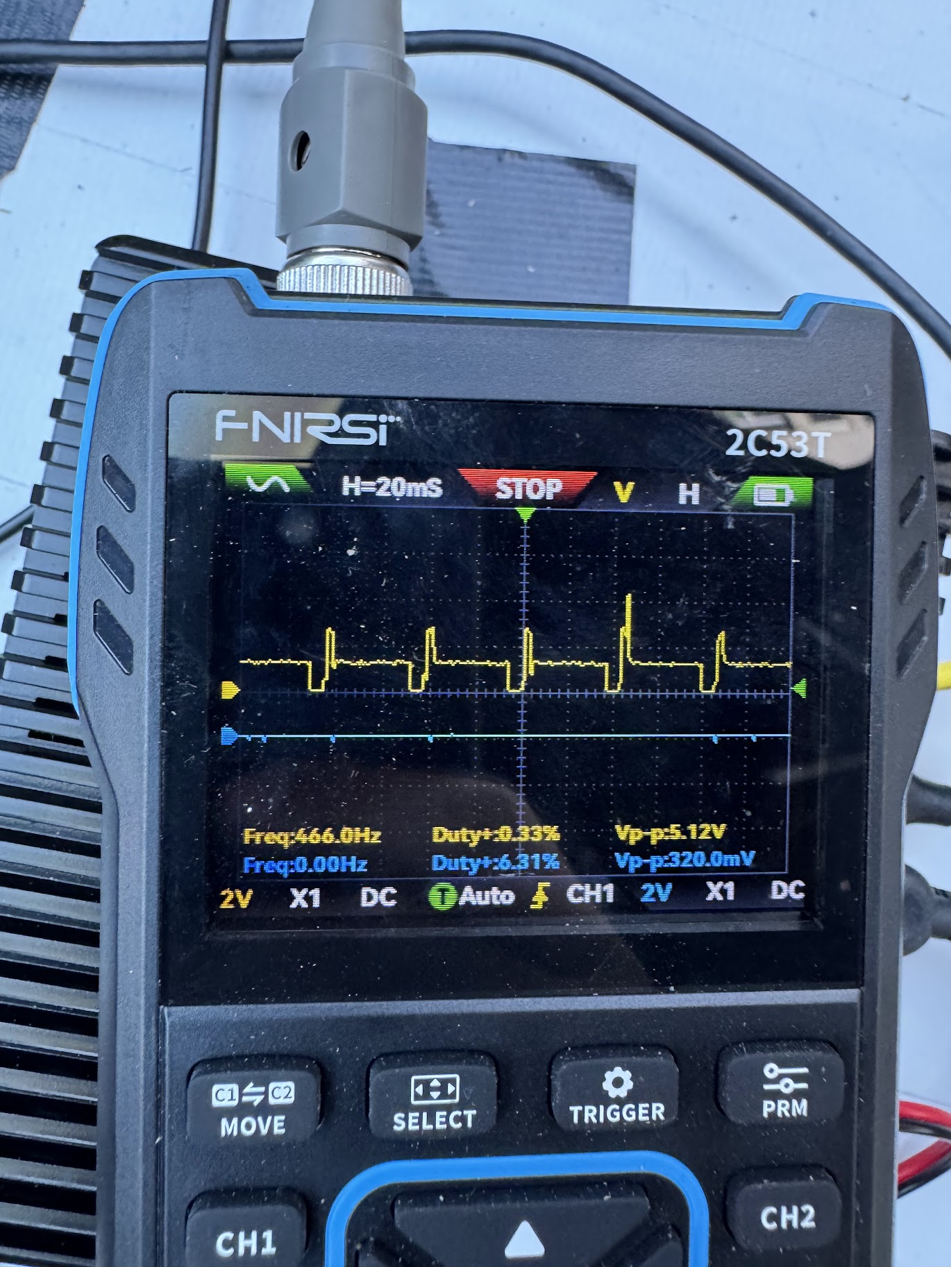
- Connect the line to an o-scope while the engine was running.
- Verify I could process the signal later.
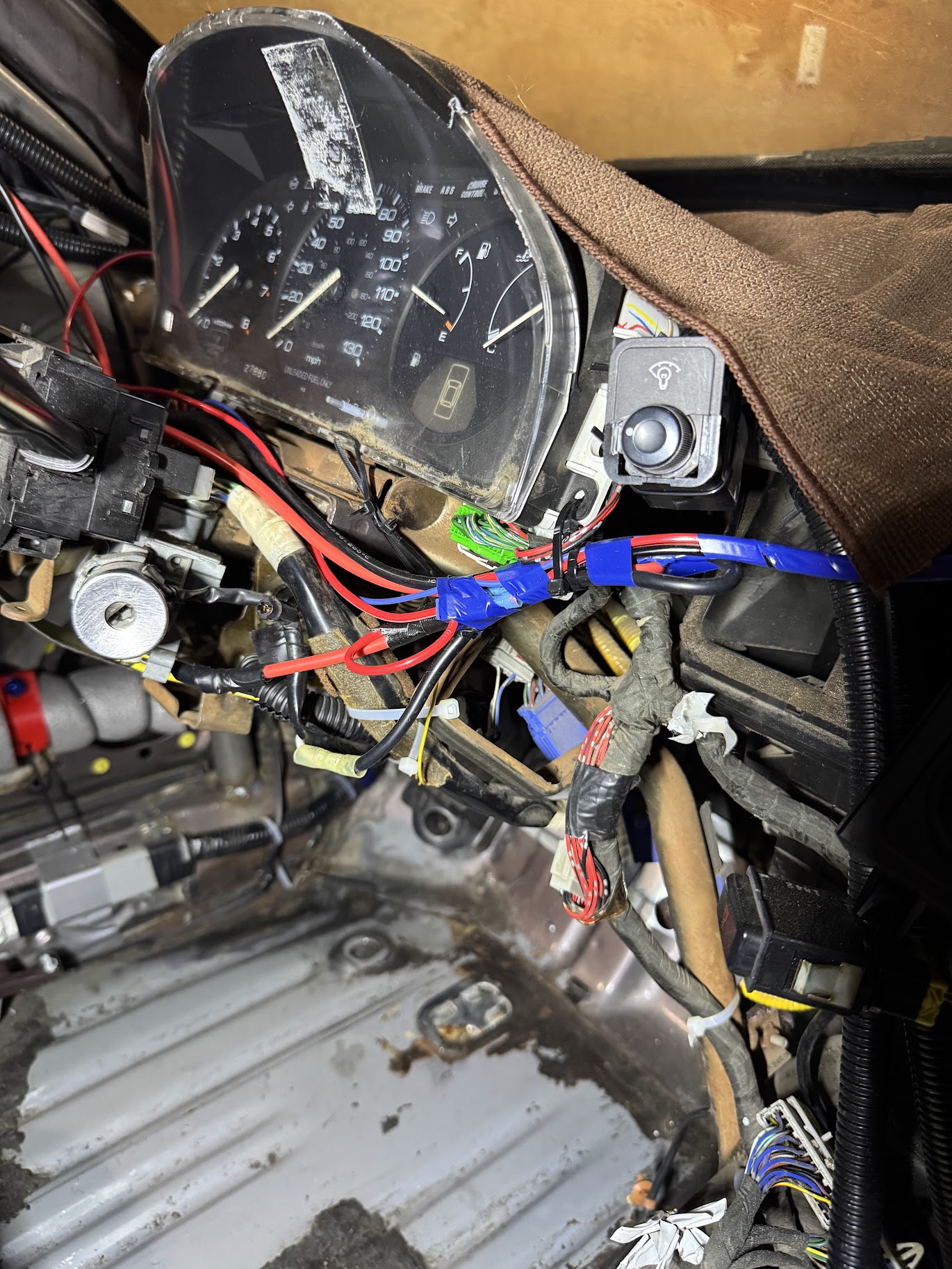
It is very helpful to buy an
extension harnessfor these kinds of jobs. The OEM harness is very tightly packed, and the plastic hasn’t been moved in years. It’s much easier to trace wires and put in taps on an extension harness that has everything all split apart already.
Telemetry Point Table
| Telemetry Point | Sense Strategy | Signal Type | Arduino Pin | Sense Line |
|---|---|---|---|---|
| Video 1 | Camera | USB | — | — |
| Video 2 | Camera | USB | — | — |
| Car Audio | Microphone | USB | — | — |
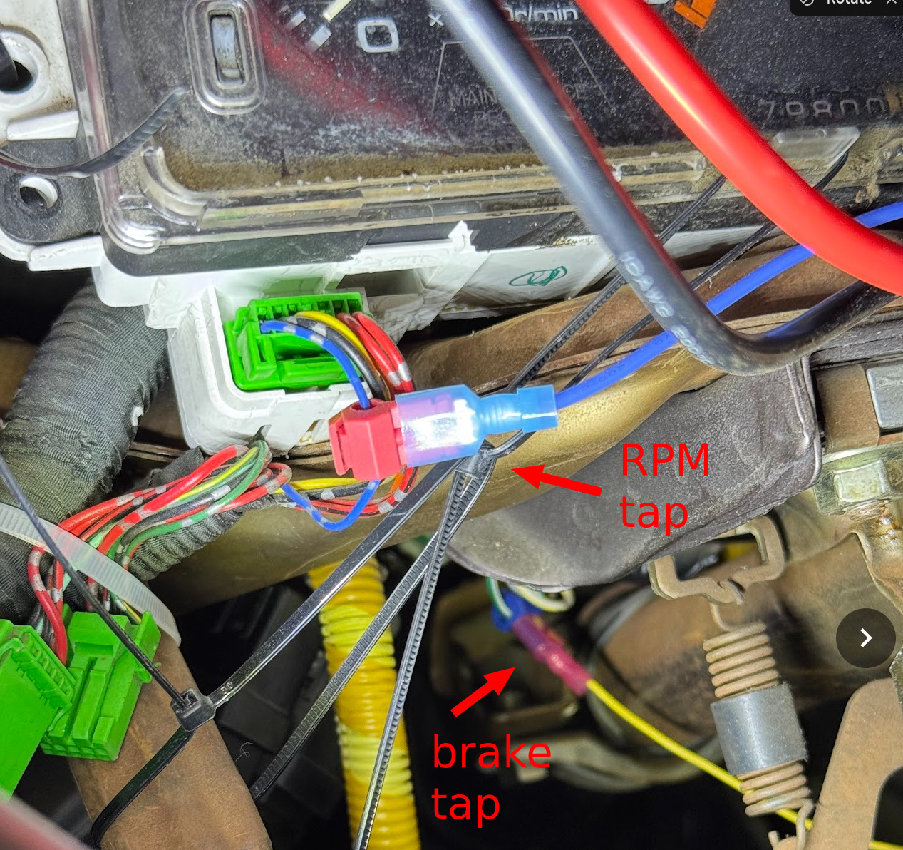
| Brake Indicator | Binary yes/no voltage | 12V analog | A5 | White/Green brake light line |
| Battery Voltage | Analog | 12V analog | A6 | Tap off PDB +12V bus |
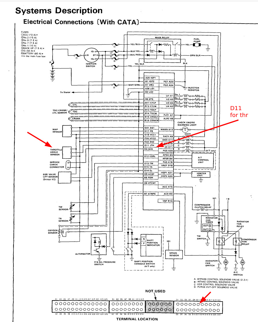
| Throttle Position | Calibrated 0–100% | 5V analog | A9 | D11 ECU D connector |
| Engine Coolant Temp | Lookup table | 5V analog | A8 | D13 ECU D connector |
| MAP | Lookup table | 5V analog | A10 | D13 ECU D connector |
| RPM (Tach) | Instantaneous pulses/sec | 12V square wave | D18 | A7 BLU Dash connector |
| VSS | Instantaneous pulses/sec | 12V square wave | D19 | B10 ECU B connector |
| GPS | RaceBox | Digital | — | — |
| Accel | RaceBox | Digital | — | — |
| Gyro | RaceBox | Digital | — | — |
Details of Tapping
Direct sense taps require a high impedance resistor in line to prevent the Arduino ESD protection diodes (when Arduino is unpowered) from pulling the sense lines low and confusing the ECU. Especially if MAP is pulled low, the car will not start.
The RPM line comes from the ignition which has a lot of noise, and can separately also spike as high as 24V or 36V. I have a diode to suppress the voltage spikes, but next time I’ll add a cap to suppress the noise.
To make the build complete, it is helpful to have:
- T-splice connectors
- Butt splice connectors
- Diodes, resistors, capacitors
- Physical switch
- Inline fuses and fuse holders
04 - Power Architecture
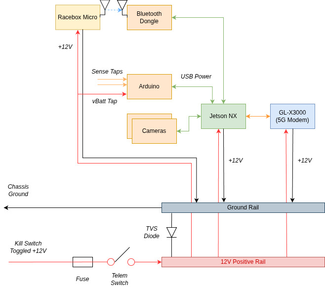
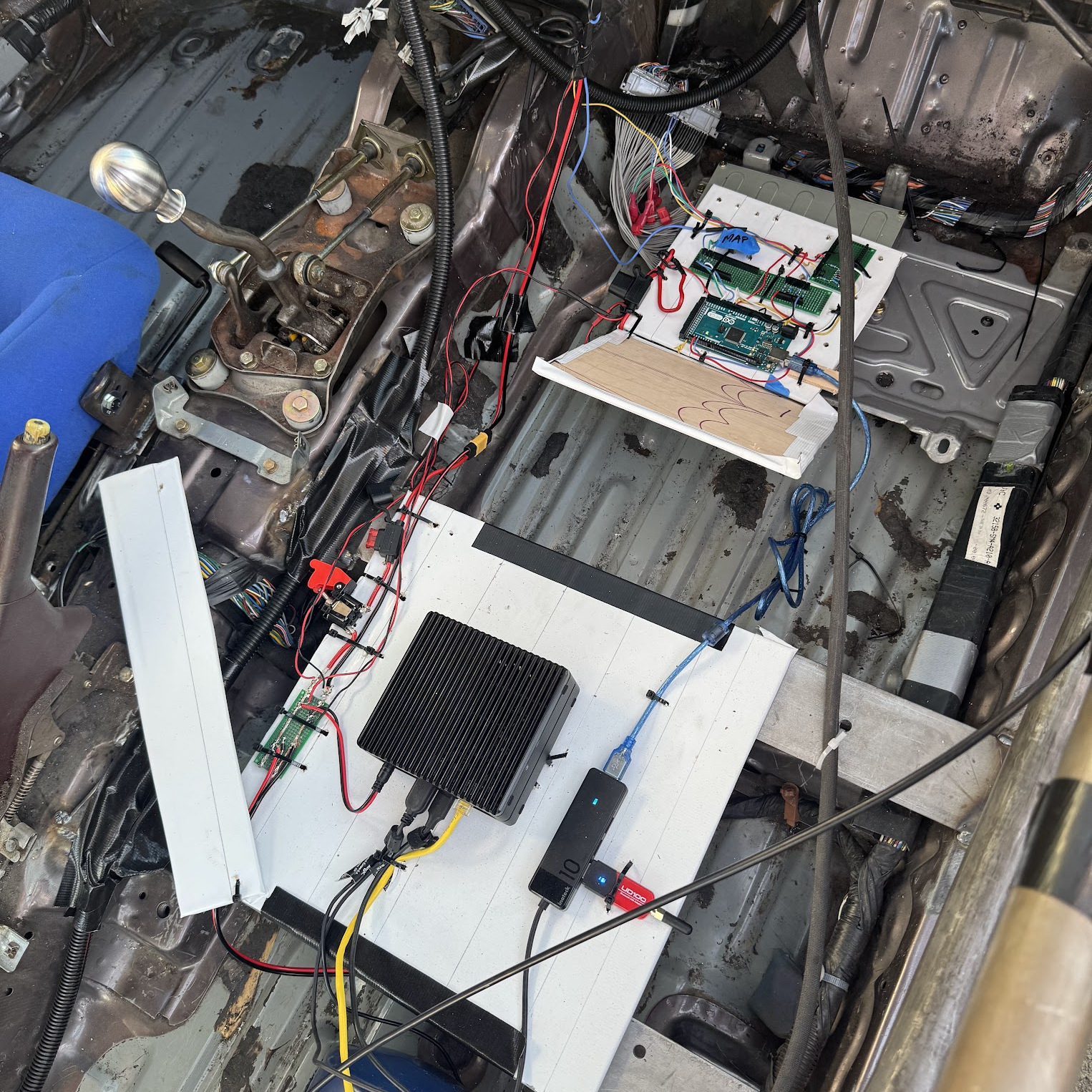
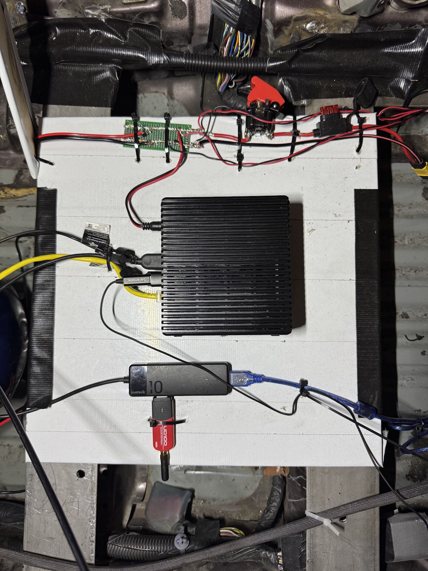
I decided to make the source of all the power the kill switch +12V downstream. This is for safety reasons so that if we pull the kill switch telemetry powers off too. The “power distribution board” was just a perf board with everything soldered up to meet it. It was jank, but it worked well. Yes it was covered later. I got very lucky that the Jetson, Modem, and RaceBox all supported automotive 12V input. That made things significantly easier.
Power Considerations
I had considered adding another secondary battery onboard, but descoped it at the time to make deadlines. The primary goal was to power as much as we could off the onboard battery to keep things simple.
05 - Testing
Jacky will likely talk more about this, but we did multiple all up integration tests on our driveway, which helped shake down many “on-startup” stability problems. To test live data while moving, we also built a race track around our city block, which is also where we made sure to get our camera mounting dialed in, as well as discovered that we needed adjustable camera gain while the stream was running.
Once everything was tested and working, that’s when I did a final pass to zip tie everything down. If I were to do this a second time, I would definitely make a PCB for this. Too many zip ties for jumper wires that shouldn’t exist haha.
06 - Places to Improve
Sensing
I really wish I had more time and could have put some caps on the RPM sense line, there’s a lot of noise which caused us to read higher RPMs than what we actually should have been seeing on track
Power
There are two big issues:
- You can deplete the vehicle battery while running telemetry which means we had to repeatedly hook up a battery charger while running telem only
- Cranking the starter brings the
+12V rail below +10Vwhich browns out the computers. This meant stalling the car and restarting the car would necessitate a power cycle, very annoying.
For the next iteration we plan to add a small auxiliary battery with:
- a relay that switches off if the kill switch is switched to cut power to telemetry
- diodes that prevent auxiliary battery from flowing to the
main electrical bus
07 - Software
I did the embedded software running on the Arduino, and Jacky did most of the software stack. This was a lot of fun working with him as a hackathon for basically 3 days straight. Check out the github here: https://github.com/shihaocao/telem
A lot of the lessons about how this kind of software has immense parallels with my time at Orchard. It was fun to basically be on the customer side of things (when discussing software goals with Jacky). I think rebuilding what we had at Orchard indicates that we got a lot of things right at Orchard.
Jacky is also writing a blog post on the software side of things: COMING SOON
Driver Communication
We ran driver communication completely parallel to telemetry. We would communicate with drivers via discord audio call. This meant that if the telemetry stack restarted, our audio communications persisted. This was very useful during hotpits when we shut off telemetry, or if we ever had to crank the starter on track.
08 - Supporting Us
If you’re interested in sponsoring our team, or donating, please reach out to me over email at shihaocao@gmail.com, or on X
You can also donate directly here: https://donate.stripe.com/9B6cN52esdN1d3LbbOcAo00
If you’re also interested in equipping your own car with this setup, for a donation to the team, Jacky and I are happy to help bootstrap you and call until the system works. We love seeing more teams have more fans cheer for them!